Enclosures & Frames
Totally Enclosed Fan Cooled
Breather / Drains
To prevent against damaging amounts of water, every standard TEFC motor is supplied with one or two drain holes in the lowest point of the motor frame. This hole can easily be closed with a tapped pipe plug. Advantage Plus and Optim® TEXP motors are supplied with automatic Breather/Drains as standard equipment. Such breathers allow the motor to drain any condensed moisture without allowing contaminants to be sucked into the motor during operation. Breather/Drains can be installed in any TECO-Westinghouse motor on frame sizes 140T or larger. Breather drains can also be installed or relocated to accommodate vertical mounting on any TECO-Westinghouse motor with the exception of Optim® TEXP due to restrictions with the certifications.
Space Heaters
Space heaters can also be installed inside the motor enclosure to heat the inside air and maintain an internal temperature above the ambient dew point. This assures that cooling air will not condense and produce moisture inside the motor. Space heaters available for motors are the wrap-around type. Space heaters are rated for operation on 120V or 240V, 60 Hz, single phase power and are installed in the stator winding end-turns. Space heater leads can be terminated in the main conduit box or auxiliary box located off the main conduit box.
Rotating Shaft Seals
Special protection is provided at the point where the motor shaft passes through the bearing housing in the form of an external flinger. This flinger keeps water, dust and other foreign matter out of the motor that might enter the motor along the shaft. All motors are furnished with a rotating neoprene flinger or machined metal labyrinth seal. INPRO/SEALS™ are optional for Advantage Plus Motors. TEXP motors are furnished with shaft seals approved for hazardous locations as defined by CSA.
Sealed Leads
Additional protection against moisture is provided by a neoprene seal through which each motor lead wire is brought out of the motor frame to the terminal box. This is a standard feature for all TECO-Westinghouse motors.
Mechanical Considerations
Motor Mounting
Installation Requirements
The factors to consider in connection with the mounting requirements of the specific installation are:
First, how is the motor to be mounted?
There are two main categories:
- Some type of base that will accommodate standard motor feet.
- Installation in such a way that a special mounting flange is required on the motor.
Second, in what position is the motor to be mounted?
The possibilities include:
- Horizontal
- Vertical
- Anglular
Third, is other equipment to be mounted on the motor?
This may include:
- Pumps
- Brakes
- Gears
- Zero-speed switches
- Tachometers
Fourth, where is the conduit box to be located on the motor frame to best meet the needs of the installation’s wiring arrangement?
Two points must be checked:
- The position of the conduit box on the motor frame.
- The position of the conduit opening.
Conduit Box Location
The standard location for the conduit box is on the right-hand side when facing the “front” of the motor. This is referred to as F1.
Definition of “Front”
There is still some confusion regarding which end of a motor is its “front.” Since this is a frequently used term, it is important that everyone is consistent.
NEMA defines the “front” of a motor as the end opposite the shaft extension. (“When a motor has a flange, the flanged end is always considered to be the “rear”).
The reason for this is that most motors are mounted with the shaft extension more or less hidden from view. Thus, the “front” is the end you normally see.
Foot Mounting
Most of the mounting problems encountered can be solved with one of the assembly combinations of a standard foot mounted motor. A thorough understanding of the basic components and how they can be positioned will result in a greater use of standard motors.
The Frame includes the mounting feet and forms the foundation for the complete assembly. It can be positioned with the feet in any plane . . . top, bottom or side.
The Conduit Box can be located on either side of the frame.
- F-1 = Conduit box on right-hand side of frame when facing “front” of motor.
- F-2 = Conduit box on left-hand side of frame when facing “front” of motor.
The conduit opening can be placed in any one of four positions by rotating the conduit box on its axis in 90º steps.
A standard motor can be adapted to any of these standard mounting methods. TECO-Westinghouse will provide motors configured as ordered, either F-1 or F-2. Price adders may apply.
Angle Mounting
Where the application requires the shaft to be at an angle to the horizontal, special attention must be paid to the motor bearings.
Grease-lubricated ball bearings are suitable for operation at any angle. However, motors equipped with sleeve bearings or slipring induction motors are limited to angle mounting that does not exceed 10º from the horizontal.
Flange Mounting
There are three basic types of flange mountings; each are designed to meet different installation requirements.
C-Flange
This type of flange is used with close-coupled pumps and similar applications where the mounting holes in the flange are threaded to receive bolts from the pump. Normally the “C” flange is used where a pump or similar item is to be overhung on the motor, which then must have feet.
D-Flange
When the motor is to be built-in as part of the machine, such as on machine tools, the “D” flange is usually selected. The mounting holes in this flange are not threaded. Bolts protrude through the flange from motor side. Normally, “D” flange motors are supplied without feet, since the “D” flange is generally used to mount the motor on the driven machine. The motor is lined up with the driven machine by tightening the bolts to press the machined surface and ring of the flange against corresponding surfaces.
P-Flange
The primary application of this flange is on such equipment as pumps and agitators where the motor is usually mounted in a vertical position on top of the equipment.
Vertical Mounting
When a horizontal motor is to be mounted in the vertical position special considerations must be made to ensure proper operation and motor life. The considerations are dependent on the motor shaft orientation.
- Shaft Down:
- Drain holes/breathers must be relocated to the lowest part of the motor and the original holes plugged. (Except TEXP Motors)
- Drip cover should be installed for outdoor applications, or if motor is exposed to overhead/spraying moisture
- *NDE bearing must be locked with a shaft locknut 5000 frames and larger or if a Roller Bearing is installed on the DE.
- C-Flange motors to be mounted on a pump must have the DE BRG locked. The only axial movement will be the internal clearance of the bearing.
* Motor shall not be subject to additional axial loading from driven equipment.
- Shaft Up:
- Drain holes/breathers must be relocated to the lowest part of the motor and the original holes plugged. (Except TEXP Motors)
- If an inpro/seal is to be used it should be suitable for vertical use with no expulsion port.
Coupling Methods
Direct Coupled
Statistics show that only about one out of five machines operate at the same speed as its driving motor. When the motor is directly connected to the load, the application considerations are different than when some intermediate means is used to increase or decrease the speed.
Direct coupling of the motor to the load is practical if the load is to run at a standard motor speed. For these applications, specify “short shaft for coupled service.”
Belt Drive
Gear-chain-drives and belt-drives are most commonly used to obtain speed reduction between motor and driven machine. In applying these drives to standard motors, two factors must be checked:
- Effect on motor bearings.
- Effect on motor shaft.
Each of these drives will impose some strain on the bearings and shaft of the motor. The amount of strain in each case establishes the practical maximum values of horsepower and speed. The maximum values shown in Figure 7 have been established by NEMA to assure good bearing life and guard against excessive shaft stress in the application of V-belt drives to NEMA standardized frames.
| Motor Frame | RPM | Max HP |
|---|---|---|
| 256T | 3600 | 25 |
| 445T | 1800 | 200 |
| 445T | 1200 | 125 |
| 445T | 900 | 100 |
Figure 7. Maximum Horsepower V-Belt Drives Recommended by NEMA for NEMA Standardized Frames
Non-Standard Belt Applications
A user may want to use a belt drive on a motor outside of the sizes listed in Figure 7. In such a situation, send all available information on the application to TECO-Westinghouse. This must include the following information:
- Belt type (A, B, C, D, or E) and size
- Number of belts
- Sheave dimensions (pitch diameter, also face width and weight)
- Direction of belt pull (whether up, down, or some other angle)
- Centre Distance
There are several things that TWMI can do depending on the application:
- In some cases, the standard motor may be suitable.
- Engineers may be able to suggest some slight change in user’s drive details to permit the use of a standard motor.
Belt Tension
All belt drives should include a means for adjusting belt tension. This may be a sliding base, slide rails or other device. The natural tendency of most operators is to run the belts too tight regardless of whether “V” belts or flat belts are being used. A good rule to remember is this – a belt that never slips is usually too tight. A properly applied belt will always slip slightly when starting under load. Tight belts shorten bearing life, and may cause vibration and shaft breakage.
Under certain conditions of excessive shaft stress, the shaft may rupture before the bearing fails.
This type of failure is usually encountered when a motor is applied to a belted load which exceeds the NEMA standard for its particular rating (See figure 7).
Bearings
Ball Bearings
All anti-friction bearings are rated on the basis of the fatigue life of the material. The “life” of a bearing is defined as the number of revolutions completed (or hours at some given speed) before the first evidence of fatigue develops.
This point is difficult to predict for an individual bearing. Therefore, statistical distribution is employed to predict bearing life on the basis of the performance of a group of bearings.
The “minimum” life of a group of identical ball bearings is defined as the number of revolutions (or hours) that 90% of the group of bearings will complete or exceed before the first evidence of fatigue develops. The “average” life is 5 times the minimum life.
Both of these factors are based on bearings running at their rated load. For loads above or below this point, bearing life varies inversely with the cube of the load: Failure of ball bearings may be caused by:
- Rough races caused by dirt …one reason why doubleshielded sealed bearings are used is to minimize the possibility of introducing dirt into the bearings.
- Metal flaking or cracking from balls or races … caused by overloading.
- Worn or broken retainer … caused by faulty lubrication or misalignment. We provide adequate lubrication and guard against misalignment by properly machining the part
- Bearing jammed by hardened grease … result of high temperature or contamination.
Using Speed-Torque Curves
A great deal can be learned about torque from speed-torque curves. A typical speed-torque for an AC squirrel-cage motor is shown on the following page. Such a curve tells what kind of jobs a specific motor can handle.
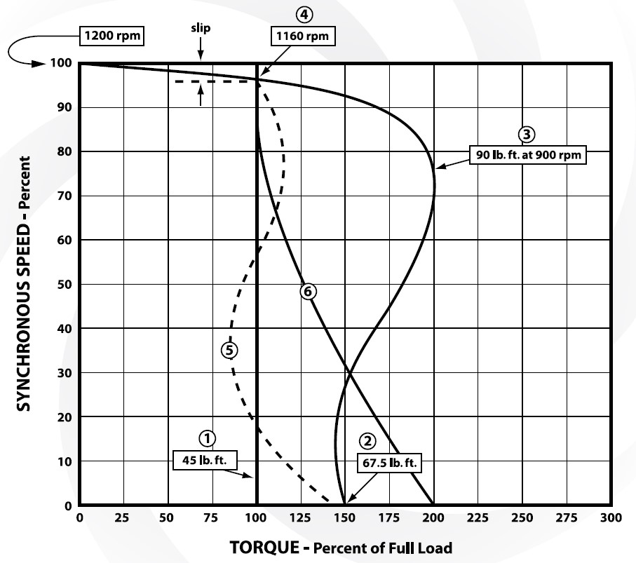
This speed-torque curve is typical for a whole family of motors, but for this discussion assume it is for a 10HP, 1200 RPM AC squirrel-cage motor. Full-load torque is listed as 45 lb-ft (1).
In analyzing the solid-line motor curve, start at (2). This is the starting torque point which is one of the critical selection factors. The value is 150% of full-load torque, which of course, is 67-1/2 lb-ft for this specific motor.
Now, moving up the curve, you see that the torque drops off a bit as the motor picks up speed, until about 20% synchronous speed is reached. At this point, the torque starts to increase and continues doing so until about 75% speed is reached (3). The motor has now reached the maximum, or breakdown, torque. The abscissa shows this point to be at 200% of full-load torque, which, when converted, equals 90 lb-ft. The speed is 900 RPM.
This is another critical selection factor, particularly where fluctuating loads are involved. No point in the duty cycle can exceed this torque value. If it does, it will stall the motor. From here on, as the motor approaches synchronous speed, the torque decreases. At (4) the motor has reached full-load torque and is operating at full-load speed which is 1160 RPM. As would be expected, it is at this point that the rated horsepower is established.
The difference between the synchronous speed of the stator’s rotating magnetic field and the speed of the rotor is termed “slip.” With this motor, the slip is 40 RPM, or 3-1/3 percent.
It is fairly obvious that as long as the torque curve of the driven machine stays to the left of the motor speed-torque curve up to the full-load point, the motor will be able to handle the job. However, should any portion of the driven machine torque curve fall to the right of the motor speed-torque curve, then a different motor must be selected.
FOR EXAMPLE:
The dotted line, labeled (5), is the speed-torque curve for a loaded ball mill. The complete curve falls within the operating area of the motor.
The dash line, labeled (6), is the speed-torque curve for a loaded rolling mill. Here you see that the required starting torque falls beyond the capacity of this motor. Therefore, a different motor will have to be used.
The motor speed-torque curve shown here is that of a NEMA design B motor. As you know, there is a number of other NEMA designs for polyphase squirrel-cage motors, … namely: A, C, D and F. Each design develops a different set of characteristics. Each design is intended for a different use.
SPEED-TORQUE CURVE – NEMA B
Environment
The Environment Check List itemizes the problem areas. If the motor is exposed to any of these conditions, provisions must be made to protect the complete motor or its parts.
An understanding of the reasons for examining each of these problems will help determine which type of insulation is needed.
Environment Check List
Ambient Temperature
- Higher than 40ºC (104º F)
- Lower than -40ºC (-40º F)
Altitude
- Above 3300 feet above sea level
Mechanical Abuse
- Shock
- Vibration
Contaminants
- Corrosive Agents
- Chemicals
- Abrasive Agents
- Dust
- Filings
- Sand
Blanketing Agents
- Dust
- Lint
- Snow
Moisture
- High humidity
- Water
Form
- Solid
- Liquid
- Gas
Method of Movement
- Suspended in air
- Falling from above
- Force directed
High Ambient Temperature
Primarily affects the insulation. It causes deterioration and accelerated aging. It also can reduce the viscosity of the greases in the bearings to the point where its lubrication value is impaired.
Since total temperature at the hottest spot and the insulation temperature capability are the governing factors, there are two approaches that can be taken.
- Use a higher class of insulation i.e. Class H in place of Class F. This would allow an extra 25ºC to be utilized to offset the elevated ambient temperature. For example, a motor designed for a Class F insulation system but built with Class H insulation could theoretically operate satisfactorily in an ambient temperature of 65ºC instead of 40ºC. Consult your local TWMI representative for individual evaluation.
- Utilize the same insulation system but increase the motor frame size. This approach will lower the motors operating temperature rise thus making part of the temperature rise capability available to withstand the elevated ambient temperature. This is equivalent to oversizing the motor horsepower.
PLEASE NOTE:
At elevated ambient temperatures, the type of bearings and the bearing lubricant would also have to be carefully analyzed.
Low Ambient Temperature
Primarily affects lubrication. It can increase the viscosity of the grease in the bearings to the point where its lubrication value is impaired, especially during startup. Extreme low temperatures can cause materials to become brittle and prone to failure such as shaft breaks or cracked stator housings.
Considerations to Design:
- -41ºC to -50ºC (-41ºF to -58º F). Low temperature grease rated to minimum -50ºC must be used to ensure adequate lubrication during startup and operation. Space Heaters are strongly recommended, especially for interment duty applications.
- Below -50ºC (-58º F). Special consideration to the frame and shaft material must be made. Ductile cast iron will be used to increase tensile and yield strength, 4140 steel will be used for the shaft material. Appropriately rated low temperature grease must be used to ensure adequate lubrication during startup and operation. Space Heaters are strongly recommended, especially for interment duty applications. Consult your local TWMI representative for individual evaluation.
High Altitude
Where the thinner air has less cooling ability, causes excessive temperature rise in the motor.
An additional factor that affects the motor’s ability to dissipate heat is the density of the surrounding air. With higher air density, more heat can be transferred. Generally the density of air at a specific location is very constant, but air density does vary with elevation; thus, when motors are installed at locations where the elevation is substantially above sea level, consideration must be given to this factor.
Standard motors will operate successfully within their normal temperature rating at elevations up to 1000 meters (3300 ft) above sea level. When motors are to be operated above this altitude, the motor design should be checked for its suitability at the required elevation.
Contact your local TWMI Representative for evaluation. When required, motor design can be modified to make them suitable for high elevation operation.
| Altitude (Feet) | HP De-Rating Factor |
|---|---|
| 3300-5000 | 0.97 |
| 5001-6600 | 0.94 |
| 6601-8300 | 0.90 |
| 8301-9900 | 0.86 |
| 9901-11500 | 0.82 |
Shock and Vibration
Mechanically abuse the complete motor causing breakage of mounting feet, frames, shafts and brackets, fatigue terminal connections, damage bearings and produce mechanical wear on insulation.
Corrosive Agents
Eat away at insulation and exposed metal parts (air-gap surfaces, bearings, and shaft)… eventually cause malfunction of these parts.
Abrasive Agents
Erode protective coatings as well as exposed surfaces, causing breakdown of insulation, score critical bearing surfaces.
Blanketing Agents
Deposit unwanted coatings on critical parts, clog air vents and passages and reduce heat dissipation. This points up the need for frequent inspection when the motor is located in contaminated atmospheres because current overload protection or ammeters on the control panel do not detect overheating of the motor caused by obstructed ventilation.
Moisture
Collects on critical parts, causes shorting of electrical components and corrodes exposed metal parts.
Motor Designs
Horsepower Formula
There are four conditions that define a motor’s performance characteristics:
- Horsepower
- Torque
- Speed
- Temperature Rise
Each is a value unto itself, but each combines with the others to produce a total result. A basic understanding of these values, individually and collectively, is necessary before any real proficiency in the application of motors can be attained. Horsepower is the term used to define the rated size or power capability of the motor and is expressed:
HP = (Torque x RPM) / 5250
From this formula it is easy to see the relationship between Torque, Speed and Horsepower. Due to the fact that motors are rotating machines, the force the motor produces to do work is expressed as Torque (discussed in detail later). Keeping this Horsepower formula in mind, Torque can be expressed as:
Torque = (5250 x HP) /RPM
It is this relationship between Horsepower, Torque and Speed that must be understood before you can safely evaluate the proper motor for any given application. Most motor applications have very specific load requirements which require certain Torque, Horsepower and Speed. The sales engineer can evaluate what size motor or what Horsepower motor will produce the Torque required to drive the load at specified speeds. For example, using the same Horsepower formula, the motor’s Speed (RPM) can be expressed as:
RPM = (5250 x HP) / Torque
If you need to know how much Torque a 200 Horsepower, 1784 RPM (4 Pole) motor can produce at full load (normal rated conditions) you would perform this calculation:
Torque = (5250 x 200HP) / 1784 RPM
Torque = 588 lb-ft
To illustrate the relationship of Speed and Torque further, we will use the same 200HP rating but change the speed to 1185 RPM (6 Pole):
Torque = (5250 x 200HP) / 1185 RPM
Torque = 886 lb-ft
In this example it is easy to see that a slower 6 Pole motor can produce significantly more torque that a faster 4 Pole motor of the same Horsepower rating. Now lets consider a customer that requires a motor that can produce 875 Lb-ft of Torque but at a Speed of 3600 RPM (2 Pole). We know from the previous example that a 200HP motor running at 1200 RPM (6 Pole) speed can produce 886 Lb-ft of Torque but, what size or Horsepower motor will produce this Torque at the faster speed of 3600 RPM?
HP = (886 lb-ft x 3600 RPM) / 5250
HP = 607.5 HP
This is a substantially larger and more expensive motor than the 200HP motor.
Torque Terminology
Torque and force are sort of blood brothers. The term “Force” is used when dealing in linear motion, and the term “Torque” when dealing in rotary motion.
Torque is a product of force (pounds) times radius (feet). Thus the value is expressed in “pound-feet” which indicates “X” the number of pounds at a one-foot radius (or any combination of radius and force whose product equals “X”).
Torque is used two ways. In the case of a piece of machinery,
torque indicates the rotational force required to drive the
machine. In the case of a motor, torque indicates the rotational
force that the motor can produce.
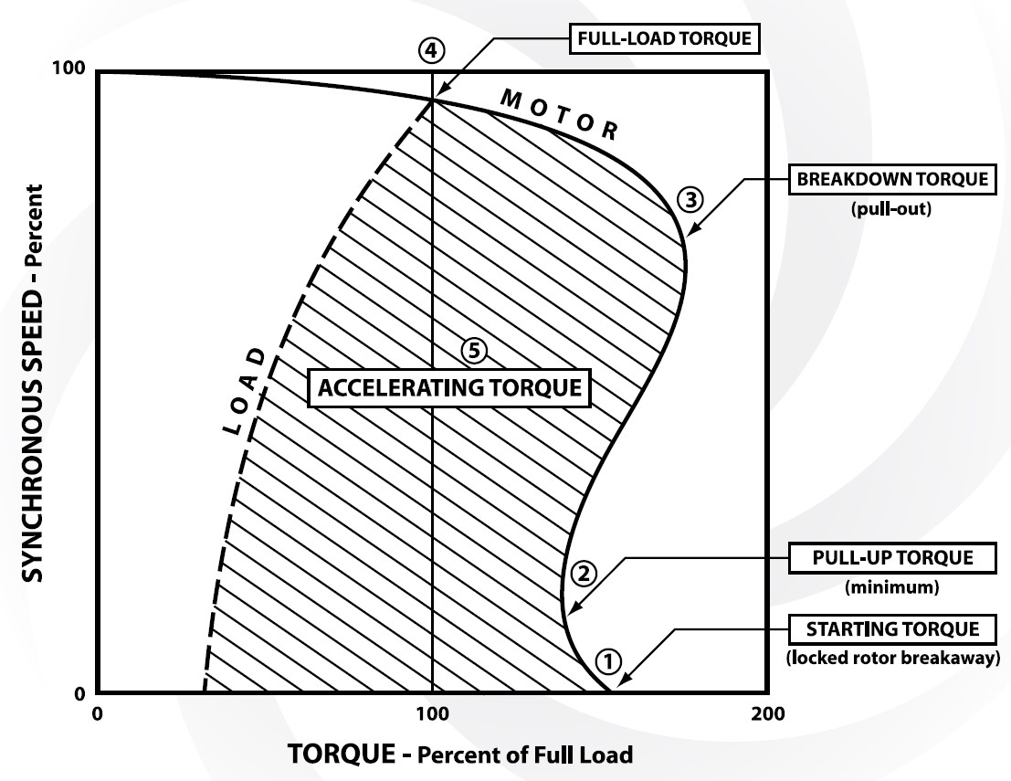
The typical AC induction motor speed-torque curve shown below illustrates some of the various types of torque with which
you will be dealing.
“Starting Torque” is the torque developed at the instant the motor is started. In essence, the rotor is stationary, but only for a moment. The arrow at (1) shows starting torque. Starting torque is also called “locked-rotor torque” or “breakaway torque”.
The next term, “pull-up torque” (also called “minimum torque”) is shown at (2). This is the minimum torque developed in the “cusp” area just above starting torque. It should be noted that many motors do not develop this cusp characteristic.
“Breakdown torque” is the maximum torque that the motor can develop without stalling. This is shown by the arrow at (3) as being the maximum value reached by the torque curve. This characteristic is sometimes called “pull-out torque”.
“Full-load torque” is the torque that the motor develops in
producing rated horsepower at rated full-load speed, as shown
at (4). You might think of this as “rated torque”.
“Accelerating torque” is the “plus” torque developed by the
motor that is beyond the torque required by the load at any
given speed. It is shown by the shaded area between the
motor-torque curve and the load-torque curve at (5).
TORQUE TERMINOLOGY
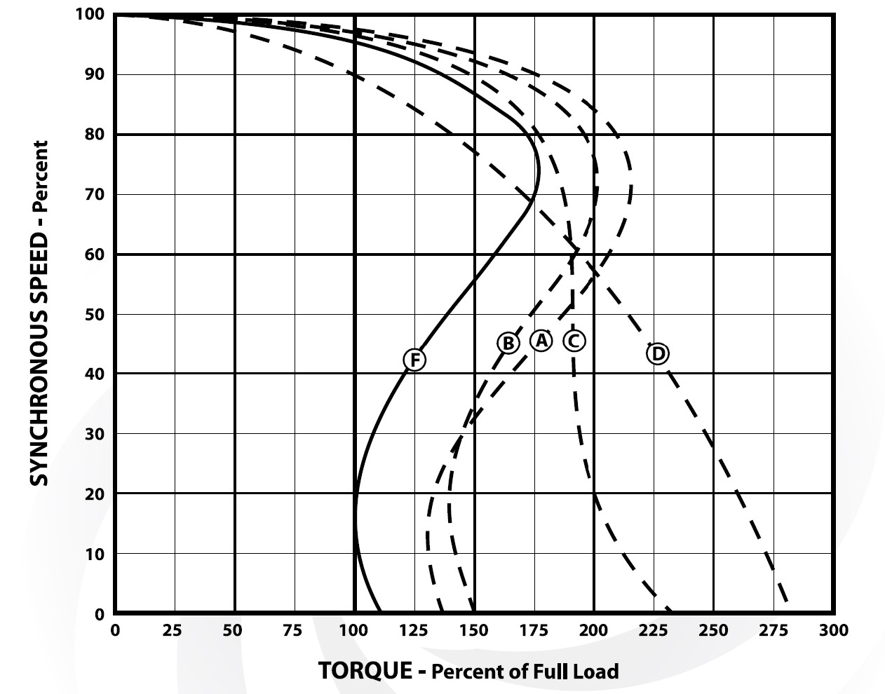
NEMA Designs A, B, C
It is important to understand the characteristics of each of these NEMA designs. In most cases you will use the standard NEMA B design. However, there will be times when an A, C, D or F design will handle the job better.
About the best way to become familiar with these characteristics is to analyze the speed-torque curves for each of the NEMA designs.
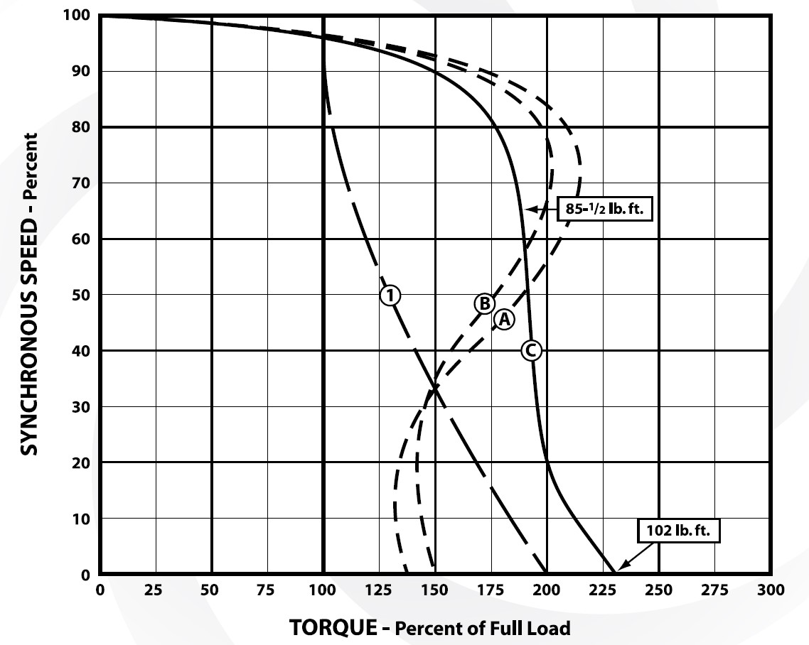
The graph shown below shows the speed-torque curves for NEMA designs A, B and C. Curve B is dotted because it was discussed on the previous page. Curve A is dotted because its characteristics are much like those of curve B. As you will note, design A has a slightly higher breakdown torque than design B.
Designs A and B are similar in basic characteristics. The difference lies in the fact that starting currents for design B motors are limited by NEMA standards. There is no limitation on starting current for design A.
As shown by the solid-line curve, a NEMA design C motor has a higher starting torque than either the A or B design. This torque is about 225% which, in the case of the 10HP example, is 101 lb-ft.
Breakdown torque, on the other hand, is lower than that for either A or B. Although there is no definite point for breakdown torque, its value is established at about 190% (10HP example – 85 1/2 lb-ft).
Full-load torque is the same as that for both A and B.
The curve (1) is the same loaded rolling mill speed-torque curve shown below . Here you see that a design C motor can handle this load because of its higher starting torque. In keeping with the basic speed-torque rule, all parts of the load curve fall to the left of the motor curve.
NEMA C motors have a double-deck rotor in which the upper deck consists of a small, high-resistance winding. This upper deck would be subject to severe heating during prolonged accelerations. For this reason, design C motors should not be used on applications requiring frequent accelerations or involving high inertia loads. The best feature of this design is its high starting and accelerating torque.
SPEED-TORQUE CURVE – NEMA C
NEMA Design D
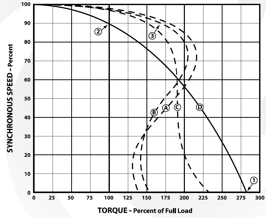
The solid-line curve in the following figure shows the characteristic of a NEMA design D motor. This design produces a very high starting torque (1) which is approximately 275% of full-load torque. However, it has no true breakdown torque, as evidenced by the fact that torque continues to decrease all the way up the speed ladder.
Another somewhat unusual characteristic of this motor is its high slip at full-load torque (2). The particular curve is that of a design D motor having a slip of 10%. However, design D motors with other values of slip are made. Two different designs have been standardized…one is the 5 to 8% slip motor, and the other is the 8 to 13% slip motor. Special designs can be made with slip values up to as much as 20%.
The characteristics of this design are useful in meeting the needs of two broad application categories. First, the high starting torque equips this motor to handle hard-to-start loads, particularly of the pulsating type. Second, the sloping speedtorque curve fits this motor for application where it is desirable to have the motor slow down during periods of peak load so that flywheel energy of the load can be released. Typical applications include press brakes and punch presses. As soon as the peak load has passed, the motor brings the flywheel back up to speed in preparation for the next peak.
FOR EXAMPLE:
A 120-ton, 6 inch stroke straight press is being used to punch 1/2 inch thick discs. The stroke length and the thickness of the metal being cut indicate that this press is doing the work only 17º of flywheel.
In order to average out the load, a heavy flywheel is used to store energy from the motor during 343º of travel, and to give up this energy during the 17º working portion of the cycle.
Energy is removed from the flywheel by deceleration…. 10% slowdown is a typical value. In the example, the average horsepower required is 40. Consider what will happen in one case where a 40HP, NEMA B motor is used; and in the other case where a 40HP, NEMA D is used.
At point (3) on the accompanying graph, the NEMA B motor is running at 90% of synchronous speed (10% slowdown) and 165% of full-load torque (65% overload). However, note that the NEMA D motor is running at just about full load (at 10% slowdown).
Actually, a NEMA B motor would never let the flywheel slow down to 90% synchronous speed, because of the great increase in torque. The NEMA B motor will try to force the flywheel to run at a much higher speed, thus overloading the motor and preventing the flywheel from giving up a large portion of the usable kinetic energy it has stored.
The advantage then, of the high-slip NEMA D motor is its ability to “roll with the punches” on flywheel applications.
SPEED-TORQUE CURVE – NEMA D
NEMA Design F
The speed-torque curve of a NEMA design F motor shows that this motor has a very low starting torque and only a moderate breakdown torque. However, this motor has one desirable characteristic…a low inrush current is required for starting.
It is understandable why the applications of design F are limited. In general, these motors are used only for easy-to-start loads where low starting currents are required and low torque are acceptable. Because of its limited overload capacity, this motor must be matched to the load very carefully. Typical applications include fans and centrifugal pumps.
SPEED-TORQUE CURVE – NEMA F
Comparison of NEMA Design Characteristics
The foregoing discussion of speed-torque curves emphasizes the fact that the five basic NEMA designs vary from one another in two important points: STARTING TORQUE and BREAKDOWN TORQUE. An overall picture of the relationship of these values is shown below.
How NEMA Speed-Torque Characteristics Are Classified
NEMA DESIGN A
- Starting Torque: NORMAL
- Starting Current: NORMAL
- Breakdown Torque: HIGH
- Full-load Slip: LOW
NEMA DESIGN B
- Starting Torque: NORMAL
- Starting Current: LOW
- Breakdown Torque: MEDIUM
- Full-load Slip: LOW
NEMA DESIGN C
- Starting Torque: HIGH
- Starting Current: LOW
- Breakdown Torque: NORMAL
- Full-load Slip: LOW
NEMA DESIGN D
- Starting Torque: VERY HIGH
- Starting Current: LOW
- Breakdown Torque: NORMAL
- Full-Load Slip: HIGH
NEMA DESIGN F
- Starting Torque: LOW
- Starting Current: VERY LOW
- Breakdown Torque: VERY LOW
Re-Lubrication Guidelines
- Frame 143T-256T: Double shielded and pre-lubricated ball-bearing motors without grease fittings and don’t need re lubrication, except on Advantage Plus products which have re-greasable features.
- Frames 280TS, 320 and larger: Motors having grease fittings and grease discharge devices at brackets. It is necessary to re lubricate anti-friction bearing motors periodically, depending on size and type of service. See Table 1 to provide maximum bearing life. Excessive or too frequent lubrication may damage the motor.
* Motors are shipped with grease for initial running however it is a good idea to add grease when the motor is first put into service, follow table 1 for the recommended amount.
Grease Type
Mobil Polyrex EM (unless otherwise specified).
Grease Quantity
The amount of grease to add per replenishment is dependent on the size of the bearing. The following table (Table 1) will provide two different quantities; “G” will provide the quantity required to re lubricate the bearing sufficiently for the interval time found in Table 2; while the second quantity “Full Qty” is the amount required to completely fill the bearing with new grease forcing the old grease out the exit tube.
Adding the “Full Qty” amount is time consuming and requires ideal conditions; old dried up grease can potentially block the exit tube leading to over greased bearings and other undesirable results. For general applications the “G” quantity is sufficient, less time consuming and has lower risk of over greased bearings. The “G” amount is based on the formula G=DxBx0.005 and is widely used in our industry.
Table 1
| Bearing Number | d (mm) | D (mm) | B (mm) | G (g) | Full Quantity (g) |
|---|---|---|---|---|---|
| NU205/6205 | 25 | 52 | 15 | 4 | 15 |
| NU206/6206 | 30 | 62 | 16 | 5 | 15 |
| NU207/6207 | 35 | 72 | 17 | 6 | 15 |
| NU208/6208 | 40 | 80 | 18 | 7 | 20 |
| NU209/6209 | 45 | 85 | 19 | 8 | 25 |
| NU210/6210 | 50 | 90 | 20 | 9 | 30 |
| NU211/6211 | 55 | 100 | 21 | 11 | 35 |
| NU212/6212 | 60 | 110 | 22 | 12 | 40 |
| NU213/6213 | 65 | 120 | 23 | 14 | 50 |
| NU214/6214 | 70 | 125 | 24 | 15 | 50 |
| NU215/6215 | 75 | 130 | 25 | 16 | 60 |
| NU216/6216 | 80 | 140 | 26 | 18 | 60 |
| NU217/6217 | 85 | 150 | 28 | 21 | 80 |
| NU218/6218 | 90 | 160 | 30 | 24 | 80 |
| NU219/6219 | 95 | 170 | 32 | 27 | 90 |
| NU220/6220 | 100 | 180 | 34 | 31 | 100 |
| NU221/6221 | 105 | 190 | 36 | 34 | 110 |
| NU222/6222 | 110 | 200 | 38 | 38 | 120 |
| NU224/6224 | 120 | 215 | 40 | 43 | 120 |
| NU226/6226 | 130 | 230 | 40 | 46 | 140 |
| NU305/6305 | 25 | 62 | 17 | 5 | 17 |
| NU306/6306 | 30 | 72 | 19 | 7 | 25 |
| NU307/6307 | 35 | 80 | 21 | 8 | 25 |
| NU308/6308 | 40 | 90 | 23 | 10 | 30 |
| NU309/6309 | 45 | 100 | 25 | 13 | 35 |
| NU310/6310 | 50 | 110 | 27 | 15 | 40 |
| NU311/6311 | 55 | 120 | 29 | 17 | 50 |
| NU312/6312 | 60 | 130 | 31 | 20 | 60 |
| NU313/6313 | 65 | 140 | 33 | 23 | 80 |
| NU314/6314 | 70 | 150 | 35 | 26 | 80 |
| NU315/6315 | 75 | 160 | 37 | 30 | 100 |
| NU316/6316 | 80 | 170 | 39 | 33 | 100 |
| NU317/6317 | 85 | 180 | 41 | 37 | 120 |
| NU318/6318 | 90 | 190 | 43 | 41 | 120 |
| NU319/6319 | 95 | 200 | 45 | 45 | 140 |
| NU320/6320 | 100 | 215 | 47 | 51 | 160 |
| NU321/6321 | 105 | 225 | 49 | 55 | 190 |
| NU322/6322 | 110 | 240 | 50 | 60 | 220 |
| NU324/6324 | 120 | 260 | 55 | 72 | 270 |
| NU326/6326 | 130 | 280 | 58 | 81 | 300 |
Procedure
- Clean grease zerk and grease gun tip
- Remove exit tube plug to allow old grease to drain
- Add grease slowly with motor running, adding amount determined in Table 2
- Allow one hour for old grease to run out, then reinstall exit tube plug
*make sure grease gun is calibrated (one pump of gun should be approximately one gram of grease)